This article concerns how to use your CNC machine to etch the reverse side of your PCB whilst getting both sides to match up as precise as possible. Why? Because when you drill the holes for your pin-mounted components and vias, they need to be in exactly the correct place, top and bottom or your board is likely destined for the bin.
There are a few ways to do this, and you may know of or have your own (better) method but here I document how I chose to do this. Hopefully, some of you will find something useful and/or interesting.
Thoughts and Plans
A few months ago I had a wooden table for my CNC machine, before that I had mounted another wooden table. In both cases I milled out a pocket of about 190mm (~7.5”) wide by 170mm (~6.7”) high. This served 2 purposes. Firstly, this flattened the bed, so that the bed would be exactly level with the Z axis (the workpiece might not be as level and it might be warped, but that’s why we need to Autolevel). The 2nd purpose was that this pocket created a left and a right edge which was perfect for aligning a PCB for double sided etching.
Since I knew the pocket was exactly 190mm wide, all I need to do when it came to etching a double sided PCB was align the board with the left edge (left edge being a X0), etch the top layer, flip the board over, aligning with the right edge of the pocket. Now, the right edge of the board is at 190mm which is precisely in line with the reverse (already etched, starting from 0) side. If I set this fixture to X0 when the machine coordinates are X190 then I should have a perfectly aligned board and can start etching the bottom layer.
This worked very well but now I have an aluminium t-slot table and don’t want to mill out a similar pocket in this because I will have to set the feed rate much slower as this is a harder material and my spindle will only do 8000rpm. max. This will take a very long time to complete, besides it will probably ruin my tool bits. So I decided to make a U-shaped jig / bracket to slot into the table to do the same thing as the pocket in my wooden table. The material used for the jig was a 300mm (~11.8”) x 150mm (~5.9”) x 3mm (~.1”) piece of aluminium sheet bought from Amazon.
Because my CNC machine is small, (the table itself is about 300mm wide by 200mm high, but the work area is only about 190mm x 170mm, hence the pocket size) the design for the jig would exceed the work area if the maximum work space was utilised and if the sheet were used in its regular horizontal position, i.e. the holes I need to cut for mounting purposes would lay outside the work area. Therefore, to mill the holes, I would need to first mark the points to cut then rotate the sheet so that its vertical in the work area, clamp it down and mill where the marks are.
Step A: Templating
You will need to design your jig in some CAD program so that you can mill from the GCode it produces, so take lots of measurements of desired sizes and spaces before drawing. In my case, my jig design was too large to fit horizontally on my CNC machine so it was necessary to print a scale drawing and tape it to the aluminium so that I could mill parts like mount holes after turning the piece to vertical in my machine.
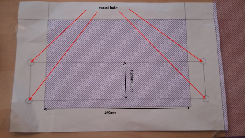
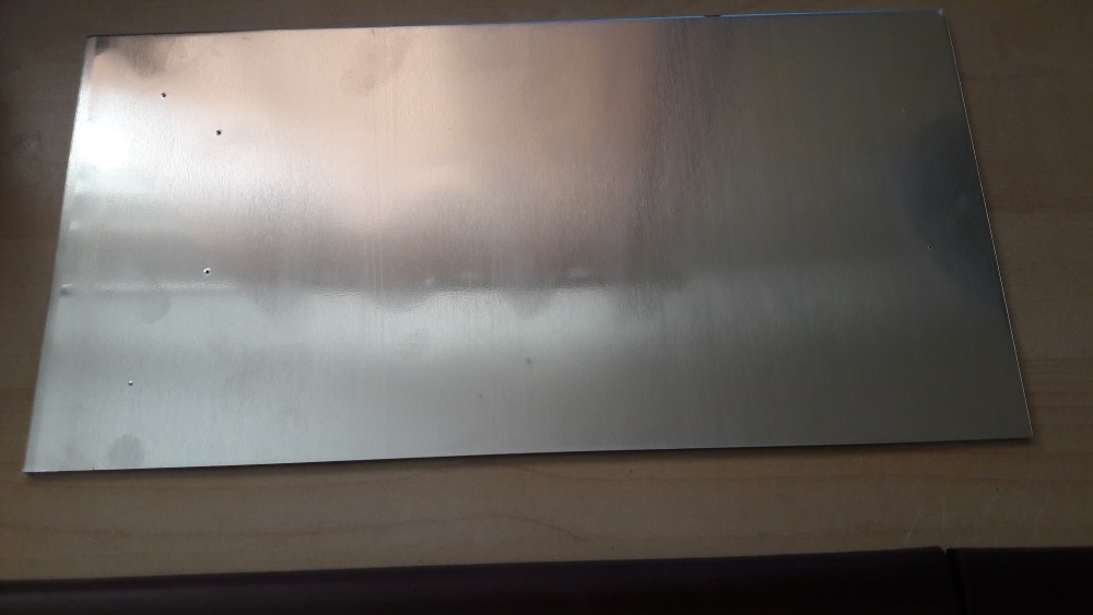
Figure 1 shows my annotated template drawing to scale printout. I trimmed the excess from the bottom and left, then taped the printout onto the sheet and used a bradawl to make the marks through the template, as shown in Figure 2.
The spacing between the centres of my t-track on my table is 50mm so that’s the spacing I have used between the mount holes on my template. Your spacing will be different of course or you may have a table without t-tracks at all and need to use a completely different design, this should give you some idea and/or inspiration though.
Step B: Mount Holes
The idea here was to cut out the holes for the t-bolts so the jig could be screwed to the table, then cut out the centre jig section whilst screwed down and fixed in position. If I cut out the centre before screwing it into position then I would not be able to mount it on the table very accurately, i.e. I want the bottom left corner of the jig cut-out to match exactly with X0, Y0 of my homed CNC machine coordinates.
I don’t want to cut through to the table either when cutting the jig centre or when cutting the mount holes. So, I would need a throwaway spoil board beneath the jig so that when cutting the jig centre it would not go through to the table, this spoil board would be taped to the underside of the jig plate so the mount holes would need to be cut through 3mm of aluminium + the 2mm thick spoil board.
This means when cutting the mount holes, I would need a 2nd spoil board to protect the table from the tool bit. Figure 3 shows the result:
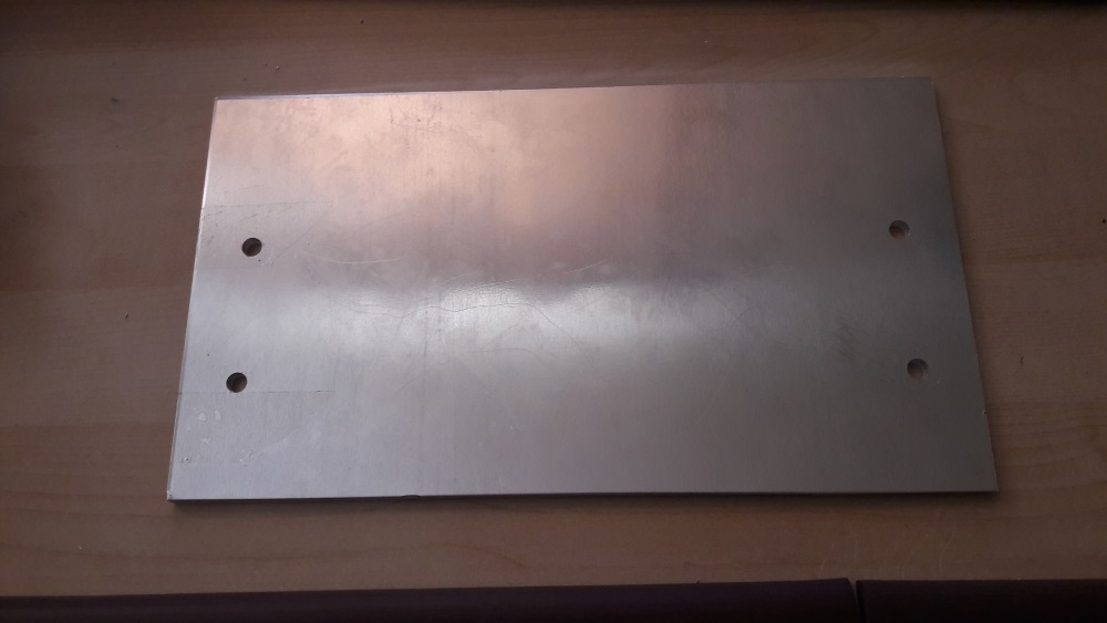
Now I can use my t-bolts to securely mount this entire fixture to my table before cutting out the centre.
Step C: Centre Cut-Out
This step is the most important in terms of accuracy because when we use this jig and place our copper board in it, it needs to be perfectly flush with both the left and right edges and we need to know the precise distance between those edges. In my case, I wanted the centre cut-out to be exactly 190mm wide as per the template in Figure 1. To do this, I would need the toolpath to be inside the line by the radius of the tool bit. My CAM program would handle this for me if I provide it with the right measurements.
To design and make the cuts I used the excellent and easy to use Vetric Cut2D. The tool diameter was measured several times with a calliper, at 3.15mm (~1/8”), meaning the radius would be 1.575mm. As I said though, Cut2D works out the toolpath for me if I provide an accurate diameter for the tool. The important thing to note here is the importance of measuring the tool diameter, in order that the left and right sides are as accurately spaced as possible and that ultimately both sides of your PCB line correctly, one above the other.
My spindle is limited to 8000rpm and when I did an earlier test cut at a feed rate of about 250mm/min (~9.8ipm) and a depth of about 1.5mm for each pass (2 passes at 3mm total) the cut was quite rough, and the edges were ragged. Also, my CNC machine sounded like it was struggling somewhat. So, I made the centre cuts at a feed rate of 100mm/min (~3.9ipm) and with 10 incremental depth passes totalling 3.5mm. With the aluminium being 3mm thick this meant I would cut through to the spoil board underneath, which was good because I did not want to leave any slightly uncut bits where bits were not entirely level. This took a few hours, but the result was nice clean cuts as shown in Figure 4.
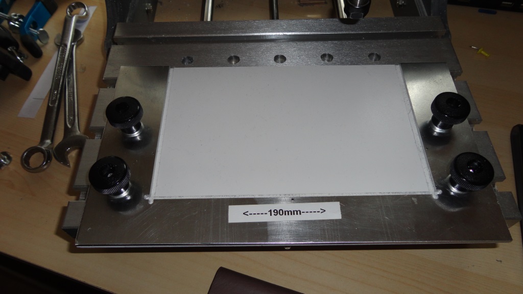
You will also notice from the figure that the bottom left and bottom right corners cross slightly. Why? Let’s say my toolpath was a rectangle drawn in my CAM program, this would mean there would be one continuous shape, so whenever the tool changed from cutting a vertical line to a horizontal one and vice versa, it would leave a small arc in the corners. This arc would be more pronounced depending on the diameter of the tool bit used.
This would push the PCB I am etching out slightly at the bottom so would not be perfectly flush with the edges. To prevent this, I used 3 separate toolpaths (3 G1 lines) which were all slightly longer than they would otherwise be causing the cuts to cross like this and preventing the corner arcs. Any copper board used in the jig should now be perfectly flush with edges.
Step D: Alignment Holes
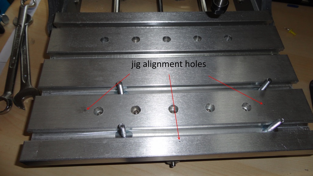
The next problem is how to realign the jig if its unscrewed some time then reattached later. The jig needs to go back on the table in precisely the same place as it is now otherwise the jig may be slightly offset from the CNC coordinates. What’s needed is a way to align the jig to the table if needs be, and this must be done before the jig is unscrewed for the first time.
My solution was to drill 3 alignment holes through the jig and into the table below then I can push some pins into the holes whenever I replace the jig on the table, tighten the mounting screws and remove the pins. Actually the holes were drilled with a total depth of 8.5mm. 3mm for the jig thickness, 2mm through the spoil board underneath and 3.5mm into the table. Figure 5 shows the holes made in the table.
Now I can unscrew the jig, remove the spoil board then screw the jig back into place after pushing the pins into the holes. I then know the jig will be in the same place it was before I removed it.
Using the jig
So how do we make use of our jig?
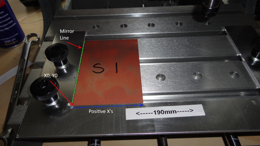
We start, as always, by homing the CNC machine. Your machine should now be at machine coordinates X0 Y0 Z0 and your tool should be directly above the bottom left corner of the centre of the jig. You will probably want X0 Y0 to be slightly inset from the edge so that your tool bit does not collide with the edges of the jig so I would move my tool 5mm inside in both the X and Y direction using the appropriate MDI command, and zero X and Y there in one of my fixtures (G55). This will be the fixture used for the top GCode file for the PCB we want to etch.
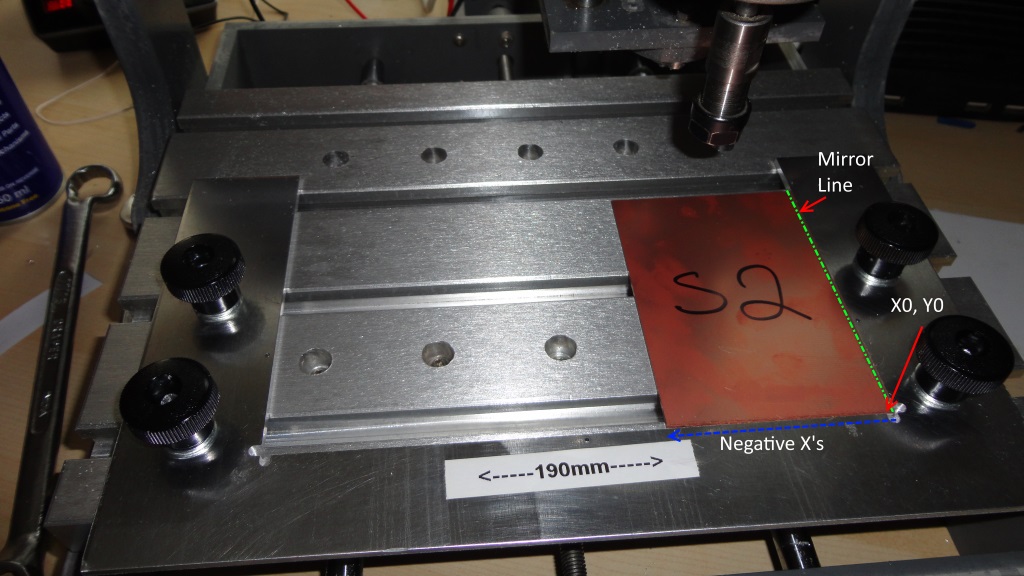
When we etch the reverse side, all the X GCode values in our bottom file will be negative so we need to use a different fixture (G56). Switch to G56 and issue the appropriate MDI commands to move X to 190mm, the tool should now be directly above the bottom right corner of the jig. Move Y +5mm and X -5mm to match the opposite side, and zero X and Y.
Of course, you could do everything all in one, rather than using fixtures at all. To do that, home the machine and use the appropriate MDI command to move the machine to the desired offset (5mm) for X and Y. Zero X and Y there and etch the top layer.
When done, flip the board and fix to the right edge. You will now need to move the tool to 5mm inside the right edge of the jig. Since we are already 5mm inside the left edge and the jig is 190mm wide, we need to move the X position 190 – 5 – 5 and zero X at that point. Etch the bottom layer. Either method will do the trick.
Clamp or use double sided tape to fix the double-sided board to the left edge. Switch to G55, load the ‘top’ file and etch the top side. Flip the board over, clamp or tape down at the right edge. Switch to G56, load the ‘bottom’ file and etch.
Figures 6 and 7 show this more visually. You can think of S1 and S2 here as 2 sides of the same page in a book, with the mirror line being the edge of the page that’s stuck to the book spine (the hinge, for want of a better word). The X’s in the ‘top’ GCode file are positive and the X’s in the ’bottom’ GCode file are negative, so both sides should match up properly when using this jig.
After etching both sides you should now be able to drill any holes that need drilling as per your drill file and the holes made should be precisely where they should be, top and bottom. I would probably clamp my board to some spoil board within my jig first though so that I do not drill into my table. Cut the board out and you’re done.
Note: An alternative to double sided tape is to use this tape and glue method as shown by Mark Lindsay CNC in this youtube video https://youtu.be/3uTsQ3dYRrk. Thanks to Arthur Eckstein (Country Bubba) for showing me this video.
Please note this documentation is not a step by step guide but simply a recording of the process I took. Feel free to modify or not the process to suit your needs. I hope someone can take inspiration from this or even just find it an interesting read.
I expect many of you have a much better jig design and can spot flaws in mine or have questions as to why I did something a certain way. Maybe it will inspire an interesting discussion on the forum. Either way, I hope this helped.
