This page documents and provides instructions for the use of some features and tools of AE. Eventually it will form part of a more complete AutolevellerAE guide, but, as AE becomes more and more fully featured, some of these features need more immediate documentation.
1. Custom Initialization Blocks
Whenever AE produces a file it will write a Z initialization block at the top of that file. The default block has the purpose of setting Z to 0 in the bottom left corner of the job before probing /milling starts so that it has a point from which all other points are based. It also ensures that your tool is properly set up before probing / etching starts.
The problem is that the default block is set up assuming that you are using the same tool for probing as you use for etching and that you have all appropriate wiring still set up for probing. This is probably true in most cases but this may or may not be what you want if you use a different probe tool for probing vs. etching for example or otherwise need to customize the initialization block.
The Z initialization block feature allows you to customize this completely so that anything added in the custom block text area will be shown at the top of the file in place of the default block. You also have the option of selecting the default routine if you want. It will be the default block which is used by default unless you tell it otherwise.
Previous versions of AE had the option to toggle the use of the default block on or off but did not have the option to use your own custom routine as it does now. Any custom routine added is saved to your settings file which is reloaded when AE starts, so you can re-use the same routine for future jobs rather than having to re-write your initialization code every time.
It is possible that you wanted a custom, blank init. for your PFG probing file but to keep the default routine for the levelled / etching file or vice versa. You can do that by setting different routines for either in the appropriate tab. See Figure 1.
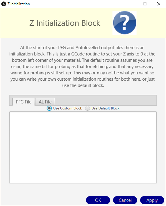
The figure shows 2 tabs ‘PFG File’ and ‘AL File’ where the initialization block can be customized for the PFG file and/or AL file respectively. But what do we mean by AL file? There are 2 types of AL file, there is the standard single AL file where all calculations are made in the same file as the etching GCode. Then there is the 2-stage AL file, i.e. the one with the RPF applied to it. If you have set a custom init. block in the AL file tab then this block will appear at the top of either type. There is only 1 type of PFG file and so the types do not need distinguishing.
Scenario
Lets say we want to use the default init. block for PFG’s but a custom block for AL files:
- Open the Z initialization block window ‘menu -> options -> Z initialization routine’
- Click ‘PFG File’ tab
- Click ‘Use Default Block’
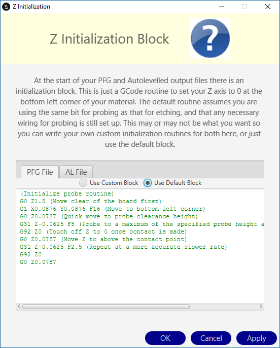
Note: To see the default block displayed in the text area as in Figure 2, you must first have a mesh set in the ‘Mesh’ tab, otherwise AE does not know what the bottom left X Y is and cannot therefore accurately display the default init. routine. You will still be able to select ‘Use Default Block’, you just won’t see it displayed here until a mesh has been set.
- Click ‘AL File’ tab
- Click ‘Use Custom Block’
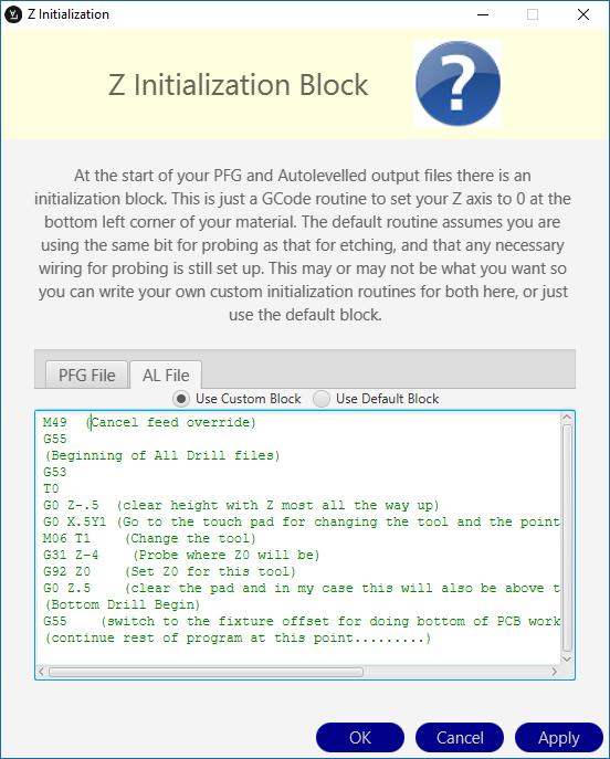
- Write or paste your custom GCode into the text area
- Click ‘Apply’ and ‘OK’
That’s all. Now each time you use AE, every PFG file will use the default initialization block and every AL file will use your custom code. If you want to make changes to this, just open the Z init. window again and make the changes you want.
Note: As all the settings and custom blocks are saved to the settings files, it is a good idea to back these files up in case they get overwritten or deleted etc. They are located in your ‘.AE’ directory in you home directory and are named ‘settings.xml’, ‘inOptions.xml’ and ‘mmOptions.xml’. Make copies and give them the extension ‘.bak’ for example.
2. RPF Fixer Tool
If you have an RPF file (that is a file containing nothing but a list of XYZ values which is the result of a probing session, probably after running your PFG file) and AE displays an error when trying to load this RPF file, then a possible cause could be that some of the XY values in the RPF are fractionally out of sync with those specified in the PFG. As a result, AE thinks you have a varying number of probe points in each row or column. AE expects the number of points to be the same for each row and column and therefore doesn’t understand this and refuses to load the RPF. The following block of code shows a typical example of this, that is the first 7 lines of such a described RPF.
X0.344 Y-2.003 Z-0.006
X10.542 Y-2.004 Z0.024
X20.743 Y-2.003 Z0.057
X30.942 Y-2.003 Z0.083
X41.141 Y-2.004 Z0.108
X51.341 Y-2.003 Z0.127
X61.541 Y-2.003 Z0.141
As you can see, some of the Y values say -2.003 and some say -2.004, so it will appear as if there are 2 rows to AE, where there is only 1 in reality.
There are several ways to fix this issue, and in the original Autoleveller, a technique was employed where the RPF is read and applies a small tolerance to the XY values. So that values are considered equal that are within ±.005 of each other for example. This works until someone needs a slightly larger tolerance, then someone needs an even larger tolerance etc. The tolerance value had to work the same for inch values as with millimetres because the RPF does not contain information as to which units are used, so this method was always considered ‘flakey’.
Another possibility is to manually edit the RPF file, changing all values to be the same as each other where they should be. For example, in the code above, you could change all the Y values to -2.003 where the value is -2.004. The same process should also be carried out for all the X values in the rest of the file. However, given this file contains 210 points in total, the method is both tedious and error prone.
The RPF fixer tool creates a new “fixed” RPF by combining the X and Y values from the PFG and the Z values from the RPF. Effectively doing the same as with the manual edit but without the tedium and error proneness. This new file can then be successfully opened in AE without any errors produced.
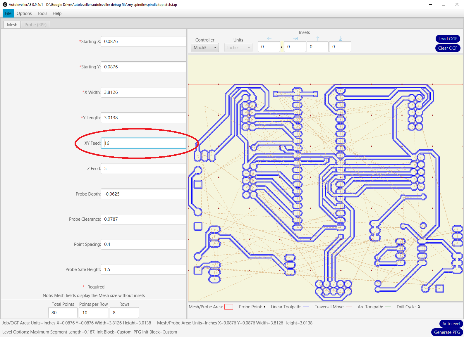
Any errors in the RPF similar to the code block above could be reduced by reducing the XY feed-rate during probing. This should reduce any under / overshoot involved when transitioning from point to point during probing. Figure 4 shows where to reduce the XY feed-rate from 32ipm to 16ipm (~800mmpm to ~400mmpm). Doing this, you may not need the RPF fixer tool at all.
File Formats
The RPF fixer tool can only ‘fix’ the RPF if the files it receives are in the correct format. Otherwise you will see an error sooner or later.
RPF
A correct RPF file format consists of lines of text where each line has at least 3 distinct decimal values, i.e. 3 number values separated by 1 or more spaces, commas, letters or anything else that might separate the numbers. Any decimal values after the first 3 in each line are ignored, and these first 3 numbers are taken as the X, Y and Z values in that order regardless of any letter placed before the number. The following formats are perfectly valid for RPF’s (only 2 points are shown from each RPF file for brevity):
LinuxCNC –
…
88.056890 11.239030 0.123968 0.000000 0.000000 0.000000 0.000000 0.000000 0.000000
77.049780 11.239030 0.152285 0.000000 0.000000 0.000000 0.000000 0.000000 0.000000
…
Mach3 –
…
1.94920,0.77490,0.00509
2.33904,0.77490,0.00514
…
TurboCNC –
…
X -1.126821Y  1.241511Z  0.004074A  0.000000
X -1.502394Y  1.241511Z  0.001093A  0.000000
…
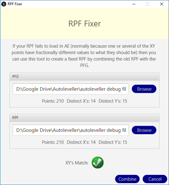
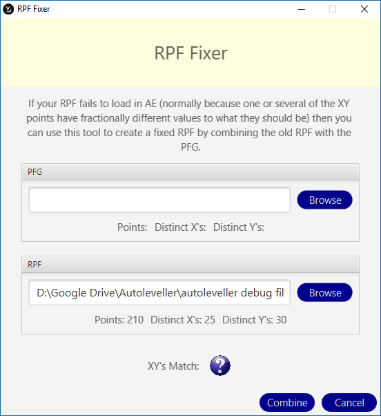
If you use a different format from some other controller, that will also be deemed a valid RPF as long as it follows the 3 distinct decimal format. If you load an RPF into the tool and it has a valid format, then it will display the number of points in that file as well as the number of distinct X and Y values as in Figure 5.
PFG
Here are some lines from a typical PFG file (again cut for brevity):
…
G1 X215.7908 Y26.47686 F750
G31 Z-1 F50
G0 Z1
G1 X189.0722 Y26.47686 F750
G31 Z-1 F50
G0 Z1
G1 X162.3536 Y26.47686 F750
G31 Z-1 F50
G0 Z1
…
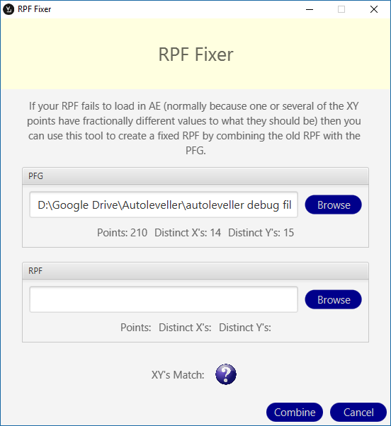
The RPF fixer tool searches the PFG file for any line which includes an X and Y value (which is the line immediately preceding a probe line, i.e. G31 in this Mach3 case). The X and Y values are converted into 2D points, which should in theory equal the number of 3D points in any loaded RPF, although the number of distinct X’s and Y’s may be different. Figure 6 shows this.
Start/end markers
There is one important aspect of the fixer tool and needs describing. Start and End markers. Without these, the RPF fixer tool will reject your PFG file, even if it is formatted correctly in every other way.
So what are these markers and why are they needed? As we said previously, the tool searches the PFG for lines containing X and Y values. The problem is, some of these lines may fall outside the probing points that we are interested in such as in an initialization block, i.e. we are only interested in the X Y’s which are logged to the RPF, not the X Y’s before or after the logging. The tool needs some way to know where to start and stop looking.
The tool uses the default Start and Stop log commands for your controller, which for LinuxCNC is…
Open log: (PROBEOPEN RawProbeLog.txt)
Close log: (PROBECLOSE)
For Mach3…
Open log: M40 (Begins a probe log file, when the window appears, enter a name for the log file such as “RawProbeLog.txt”)
Close log: M41 (Closes the opened log file)
For TurboCNC, is now:
Open log: (RPF OPEN)
Close log: (RPF CLOSE)
And whatever you set if you use a custom controller.
These markers already exist in the vast majority of previously generated PFG’s, so you wont need to make any edits there. But some, older PFG’s such as those generated for TurboCNC users, you will need to add the Open and Close markers yourself, otherwise the RPF fixer will display an error when you try to load your PFG.
Generate a temporary PFG and open it in a text editor to inspect its contents if you are unsure what this means.
Scenario
So, you have just probed an area and have an RPF but it is reporting error when you try to load it into AE. If you still have the PFG from which the RPF was created, then you may be able to fix the problems with the RPF fixer tool. To load it, select menu -> tools -> RPF Fixer. Now click ‘browse’ in the PFG section and select your PFG. Do the same thing in the RPF section to select the troublesome RPF.
If both loaded correctly then the tool window should look something like Figure 7. If not, refer to the file format section above to make sure the files are valid.
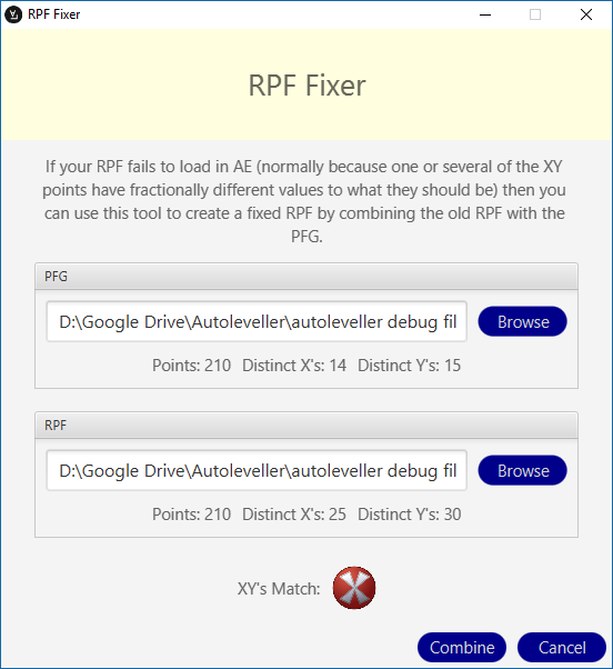
Notice that this figure shows that the total number of points in both files are the same but that the X and Y values differ. This is exactly what we expected from a ‘troublesome’ RPF and unmatched X’s and Y’s are the reason why we are running the RPF fixer tool in the first place. In fact, the number of points in both files needs to be identical for ‘combine’ to work.
Click ‘combine’ and choose a file name for the new ‘fixed’ RPF. The PFG and old RPF are now merged into one. Here is the first 7 lines from the ‘fixed’ RPF where the old RPF is the same file shown earlier…
X0.344 Y-2.003 Z-0.006
X10.57 Y-2.003 Z0.024
X20.796 Y-2.003 Z0.057
X31.022 Y-2.003 Z0.083
X41.248 Y-2.003 Z0.108
X51.474 Y-2.003 Z0.127
X61.7 Y-2.003 Z0.141
Notice how all the Y values are the same number now (-2.003). The X values have also changed to match those in the PFG. If you now browse for and load the fixed RPF in place of the old RPF, you should see that the XY’s now match as shown in Figure 8. You should also now be able to load this new RPF into the main AE and receive no more errors.
