How to use AutoLeveller
Autoleveller Guide (French PDF)– courtesy of François Gasparoux (.pdf download)

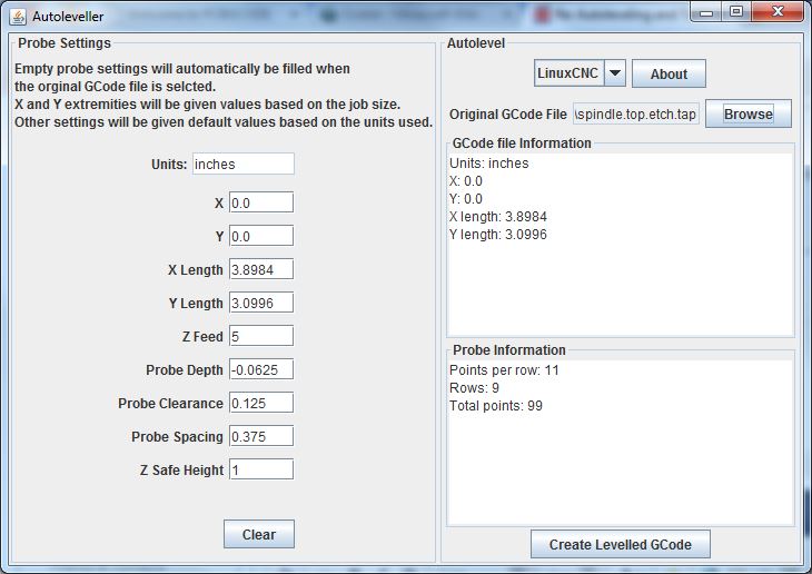
The software itself is designed to be as simple to use as possible. The above figure is the GUI layout of AutoLeveller version 0.7. It automatically gets the extremities from the input file (as well as detecting millimeters or inches) and fills in the settings for you. Default values are also provided for probe spacing etc. The effects of changing the extremities and probe spacing are reflected in the probe information box where the total number of probe points are displayed.
In this figure, LinuxCNC has been chosen as the control software, the original file chosen is called ‘spindle.top.etch.tap’ which was generated by pcb-gcode. The output file will be called ‘ALspindle.top.etch.ngc’ by default, but can of course be charged to whatever you like.
The probe X and Y settings match the board size, i.e. it is 3.8984″ by 3.0996″, which can changed as well. If you are a neat freak, you might want to change this to 4″ by 3.1″ for example or you might want to set a much smaller area to level only the area you are interested in.
Each probe uses a 5″ per minute feed rate by default and it will probe directly down until Z = -0.0625″ if no contact is made before it reaches this depth.
Each probe will return to Z = 1/8″ before moving to the next X Y probe position (this probably could be much lower but I am being ultra careful here).
The space between each probe point will be about 3/8″ and Z will return to 1″ at the end of probing.
How to use AutoLeveller with your CNC control software
The file generated by AutoLeveller can be loaded into your control software where there will be a probing stage followed by the etching stage.
NOTE: The generated file is confirmed to work in linux CNC version 2.5.x and above and current version of Mach 3.
- I like to zero my x and y about 5mm inside the material edge so that the probe tip will be directly above the board along the bottom and left edges and there is no chance of ‘missing’ these edges when probing.
- Make sure you have a working probe and that the circuit is correctly made. More than once I forgot to attach the ground clip to the spindle causing the tool to bury itself in the board and break during probing.
- Touch-off Z to zero slightly less than 10mm above the board. The first probe will move to Z = -10mm (i.e., it will probe downwards 10mm from wherever Z 0 is currently set at) and set Z to zero again once contact is made. (later versions now ask you to zero Z on or slightly above the surface)
- For a simple probe, use the tool you will etch with connected to ground and probe-in pin as shown in the video clip.
- Once the probing stage finishes, the program will pause to allow you to remove any probe clips. Don’t remove anything that might disturb the board though. Cycle start again to unpause and start etching.
- If the tip of the V-bit breaks, and / or there are ‘air cuts’, you will need to re-probe the surface.
Probe log levelling (as of version 0.8)
To create a probe-only file…
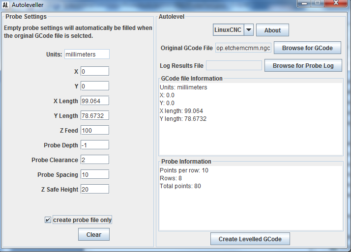
1. Open the AutoLeveller, select your etching file and check the “create probe file only” box
2. Adjust any probe settings you need to

3. Click “Create Levelled GCode” and choose a file name to save to
Probe Logging
1. Take this new “probe only” file to your CNC machine. This will probe the surface as before and log the probe information in a separate file
NOTE: TurboCNC users must delete their POINTS.DAT file before a new probing session because all probing results are appended to this file in TurboCNC, the file is not overwritten. So for a fresh file you need to clear previous data by deleting it. (TurboCNC will recreate POINTS.DAT if it does not exist)
2. Home, touch off X and Y as you need
3. Touch off Z on or slightly above the surface
NOTE: I touched off X to +17mm to avoid my clamps on the left edge of my PCB, Y to +5mm to inset the tool from the bottom edge.
4. After running the probe file, a new log file should be created in your main settings folder for LinuxCNC or where-ever you selected for Mach3 or in the POINTS.DAT file for TurboCNC
5. Inspect this log file for any problems or irregularities and re-probe if necessary
NOTE: As with the above screenshot, there should be 10 unique X values, 8 unique Y values and a total of 80 probe points in this file. Also, check the Z-values for any that look out of place. (you may need to wipe your work-piece to remove any particles and re-probe)
Generating a GCode file based on your log
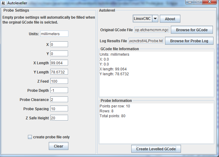
1. Open AutoLeveller again and input your original GCode file again as well as your new probe logged results file
2. Click “Create Levelled GCode” and your new GCode file is created.

NOTE: You will notice that Z values are now pre-calculated within AutoLeveller from the probe results file. The probe results table is formatted and appears at the top of this GCode file, we may need to refer to this later if our tool tip breaks for example and we need to reset Z
Recovery / Resuming

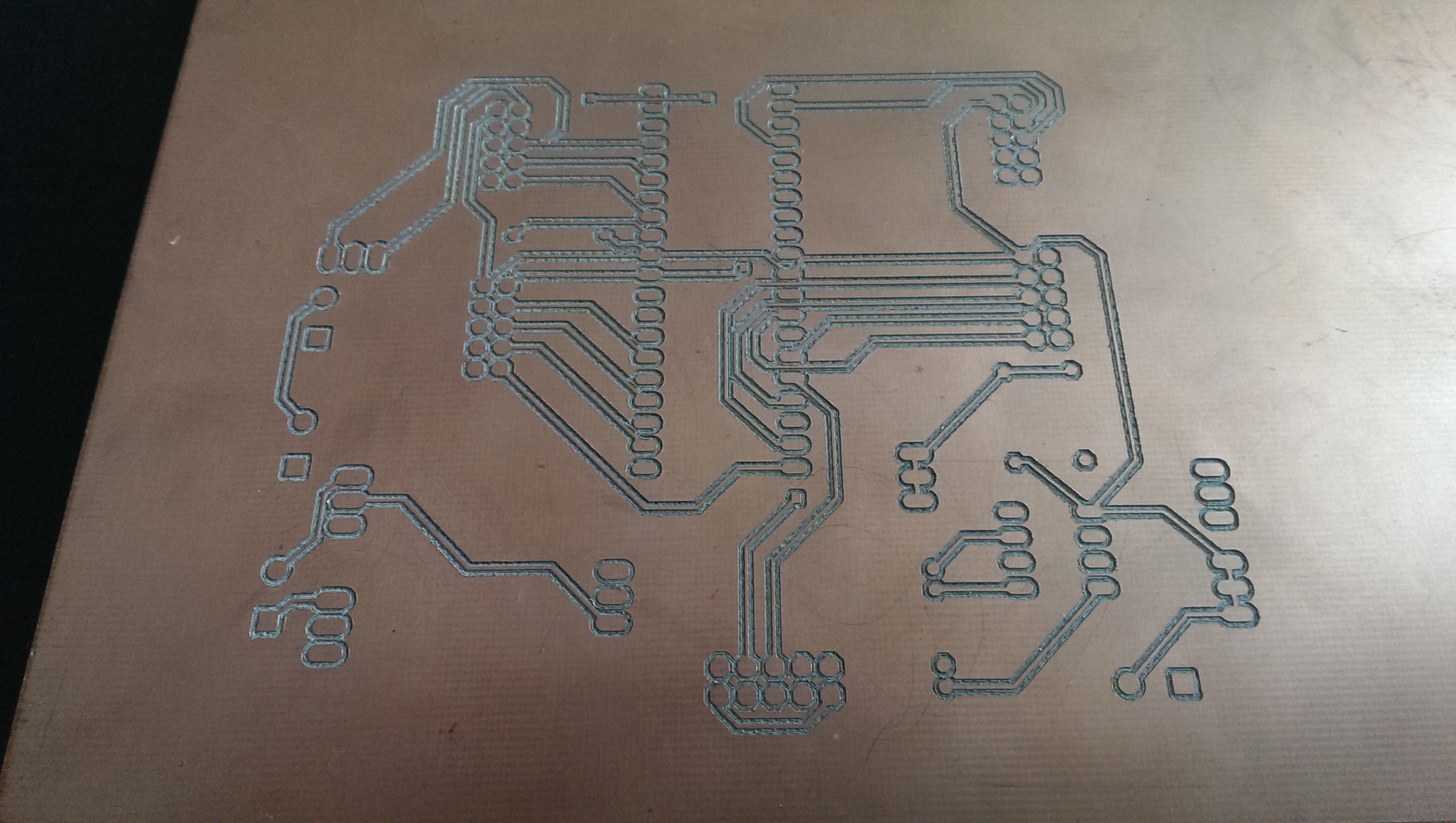
This board was etched with version 0.8, using the probe logging technique. The board was etched over 3 separate sessions, each time resuming from the GCode where I left off rather than restarting from the beginning. This resuming / recovery may be necessary if your tool tip breaks / you replace the tool or just want to re-do an earlier section for whatever reason etc. This, of course, was done without the need to re-probe the entire board, as with earlier AutoLeveller versions.
In general, to recover and resume from a line in our GCode file, we first need to re-touch off Z to one of the known and previously probed points then return to the point where you want to resume at. This can be achieved with a string of MDI commands entered manually, but there is a safer option of using the provided sub-procedures.
There are 2 sub-procedures which must be called just before the line we want to resume at. This means editing the GCode file and reloading the file back into your controller software.
1. To re-touch off Z, first note the line where you stopped. Refer to the “point order table” at the top of the GCode and select an index for one of the “clear” points (is still conductive, i.e. has not been etched already and is not cut off from your probe wire)
2. Use the index to find the probe point in the list below
3. Call the o100 sub-procedure passing the X, Y, Z coordinates from the table
This is the GCode used to create the board shown above (complete with modifications) download here…
The first session ended on line 2140 so I took a few steps back to make sure I didn’t miss anything and added the 2 lines calling the sub-procedures on lines 2100 and 2101. Similar lines were added for the final session at lines 6523 and 6524
From the points table at the top of the GCode file and board design we can see the index at point 70 is clear to use to reassign the Z axis at the start of the second session, so in LinuxCNC add the line…
o100 call [99.064000] [67.434170] [0.160613]
In Mach3 you need to fill the parameters #500, #501 and #502 for the X, Y and Z before calling the sub procedure.
#500 = 99.064000
#501 = 67.434170
#502 = 0.160613
M98 P100
4. To return to the desired line, add a call to o101, just after the o100 call and just before the line you want to resume from, passing the X and Y coordinates as arguments.
Here is a snippet from the modified GCode file…
G1 X80.904 Y49.4068 Z-0.0133
G1 X81.2006 Y49.1102 Z-0.01409
G1 X82.2194 Y49.1102 Z-0.01351
G1 X82.9398 Y49.8306 Z-0.01075
G1 X82.9398 Y50.8494 Z-0.00741
G1 X82.2194 Y51.5698 Z-0.00551
o100 call [99.064000] [67.434170] [0.160613]
o101 call [81.2006] [51.5698]
G1 X81.2006 Y51.5698 Z-0.00616
G1 X80.4802 Y50.8494 Z-0.00892
G1 X80.4802 Y50.3932 Z-0.01038
G1 X75.4802 Y50.3932 Z-0.01196
G1 X70.4802 Y50.3932 Z-0.01042
G1 X65.4802 Y50.3932 Z-0.00879
G1 X60.4802 Y50.3932 Z-0.00642
G1 X57.2077 Y50.3932 Z-0.00487
G1 X57.3086 Y50.4942 Z-0.00473
You can see the 2 lines added…
o100 call [99.064000] [67.434170] [0.160613]
o101 call [81.2006] [51.5698]
Again, in Mach3 you need to assign values to the parameters #500 and #501 for X and Y respectively before calling the sub.
The Mach3 GCode would look like this…
G1 X80.904 Y49.4068 Z-0.0133
G1 X81.2006 Y49.1102 Z-0.01409
G1 X82.2194 Y49.1102 Z-0.01351
G1 X82.9398 Y49.8306 Z-0.01075
G1 X82.9398 Y50.8494 Z-0.00741
G1 X82.2194 Y51.5698 Z-0.00551
#500 = 99.064000
#501 = 67.434170
#502 = 0.160613
M98 P100
S20000 (make sure a desired spindle speed is set if starting from cold)
#500 = 81.2006
#501 = 51.5698
M98 P101
G1 X81.2006 Y51.5698 Z-0.00616
G1 X80.4802 Y50.8494 Z-0.00892
G1 X80.4802 Y50.3932 Z-0.01038
G1 X75.4802 Y50.3932 Z-0.01196
G1 X70.4802 Y50.3932 Z-0.01042
G1 X65.4802 Y50.3932 Z-0.00879
G1 X60.4802 Y50.3932 Z-0.00642
G1 X57.2077 Y50.3932 Z-0.00487
G1 X57.3086 Y50.4942 Z-0.00473
TurboCNC is similar to Mach3…
G1 X80.904 Y49.4068 Z-0.0133
G1 X81.2006 Y49.1102 Z-0.01409
G1 X82.2194 Y49.1102 Z-0.01351
G1 X82.9398 Y49.8306 Z-0.01075
G1 X82.9398 Y50.8494 Z-0.00741
G1 X82.2194 Y51.5698 Z-0.00551
#500 = 99.064000
#501 = 67.434170
#502 = 0.160613
N200 M98 O1000
S20000 (make sure a desired spindle speed is set if starting from cold)
#500 = 81.2006
#501 = 51.5698
N201 M98 O1001
G1 X81.2006 Y51.5698 Z-0.00616
G1 X80.4802 Y50.8494 Z-0.00892
G1 X80.4802 Y50.3932 Z-0.01038
G1 X75.4802 Y50.3932 Z-0.01196
G1 X70.4802 Y50.3932 Z-0.01042
G1 X65.4802 Y50.3932 Z-0.00879
G1 X60.4802 Y50.3932 Z-0.00642
G1 X57.2077 Y50.3932 Z-0.00487
G1 X57.3086 Y50.4942 Z-0.00473
Then you just need to reload the file into your control software and resume from the first edited line.
