Guide: How to set-up a basic DIY electrical probe for CNC machines
Hardware Setup
If we want to find the top (Z zero) of a piece of material automatically and accurately many people will create a basic probe for their CNC machine. For this in general we want to either create or break a circuit whenever our tool touches the surface to be measured. The creation of this circuit will immediately trigger an input pin on the controller which essentially says, ‘the tool is touching’ In our software later we will use one of the spare input pins on our control box and wire that either to a metallic plate or directly to surface such as a blank piece of copper for a PCB or maybe some other metallic surface such as an aluminium box cover. The important thing to note is that the surface must be metallic for current to pass through. If you want to zero a piece of wood for example, you generally use a touch plate.
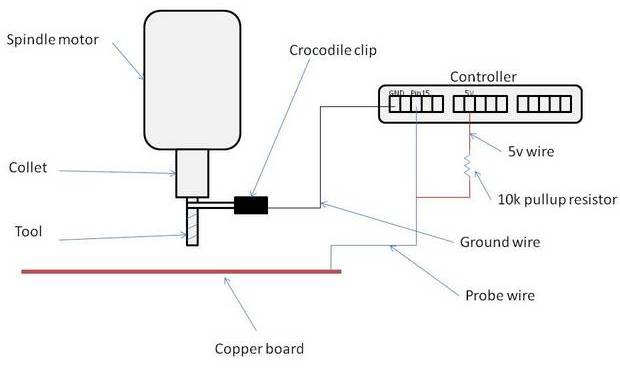
The other end of the circuit must be grounded, which means the tool (see figure 1). So connect a clip to the tool and wire that to GND on your controller. Sometimes the tool maybe grounded anyway but this GND may be intermittent and less reliable so, it is recommended to use a separate clip to be sure.
Ingredients
Assuming you have everything apart from the probing element. i.e spindle, controller, tools:
- A conductive piece of flat metal surface such as a scrap piece of copper board to make a touch-off plate
- crocodile clip to attach the ground wire
- wire to create your circuit
- 10k pullup resistor (.25W or more)
- calliper to measure the touch off plate thickness
- solder and soldering iron to secure the connections
Wiring
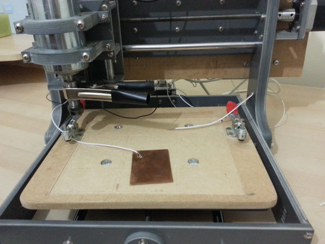
Figure 2 shows my CNC machine. You can see the big clip around the collet. This is the ground clip and for this I have soldered some wire to the handle end, the other end of the wire is screwed into the control box (GND pin) at the back of the machine. Just remember to remove this clip after probing and before the spindle starts up.
I then have 2 wires both connected to pin 15 on my control box. The first is connected to a touch-off plate via a blob of solder and is used to find the Z height for some non-conductive material such as wood. The second wire is just loose which I can just tape or clamp to the corner of a PCB or other conductive surface.
In my setup I didn’t seem to need the pullup resistor of figure 1 (some Breakout Boards include one directly on the pin or may have a pulldown resistor that is undesirable or it might be configurable via a jumper, check your controller / board documentation) but you should add it anyway to ensure the signal does not float.
Touch-off plate
We need a plate like this to accurately set Z to zero at the surface of the material where a non-conductive material is used. We first need to measure the thickness of the plate we are using with a tool such as a calliper. The plate I use is 1.54mm thick.
What we do is place it on the material that we want to mill, move the tool directly above it and use a line of GCode (this line varies between post-processor software) to probe directly down at a fairly slow feed. Once the tool touches the plate it will stop. We should touch-off Z to 1.54mm (in my case) then raise the spindle so the plate can be removed. If we then move our spindle to Z 0, the tool should touch the surface exactly.
So, the 3 steps here are:
- Probe directly downwards
- Touch-off Z to the thickness of the touch-off plate.
- Jog or otherwise raise the spindle to remove the plate
These steps are or can often be automated to run one after the other in the software.
Metallic surfaces
When you mill or etch a conductive surface you won’t need to use a touch-off plate because the surface itself can be used to probe. All you need is loose wire like the one in figure 2 which can be pinned to the surface somehow. The other end is connected to the same pin 15 on the control box. This is how I etch a PCB.
Software Setup
In general your software just needs to know where the probe is connected and whether it should be active high or active low. For example, both of the wires in figure 2 are connected to pin 15 and will trigger whenever a ground signal is detected, otherwise a constant 5v current is supplied; so it should be active low.
We also need to double check that the probe is set up correctly by touching the ground wire to the surface and checking the relevant pin ‘lights up’.
Mach 3
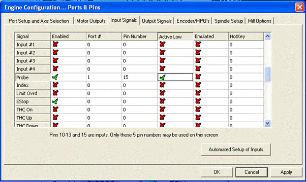
Assuming you have everything else already setup (motors, switches etc.) and just need the probe configured. Go to config ->ports and pins, and switch to the ‘input signals’ tab.
In the ‘probe’ row enable it and set ‘active low’. Assuming you only have one port, set ‘port #’ to 1 and ‘pin number’ to the pin your probe is plugged into. Mine is 15, see figure 3.
Apply and OK.
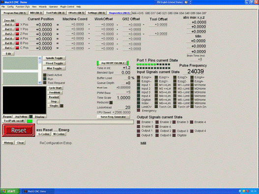
To test it works, switch to the Diagnostics screen (Figure 4) and tap your ground clip on the probe surface. When you do this and if everything is setup correctly, ‘Digitise’ will light up.
You should do the same test every time you use the probe to ensure there are no dislodged wires.
LinuxCNC
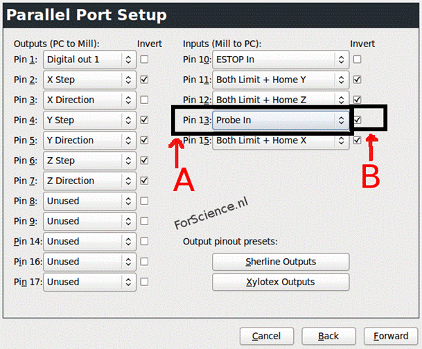
There are essentially 2 methods for configuring the probe in LinuxCNC. The first, as in figure 5 uses a graphical wizard. This is very easy but will write over any previous changes made so make sure you make backups of the .hal and .ini files first.
Change pin 13 or whatever your probe is wired to, to ‘probe in’, check the ‘invert’ box also.
Now, whenever you run some GCode file that uses the probe, it will be checking pin 13.
You can also manually add a line in your .hal file to do the same thing. Add the line in bold to your .hal file.
.hal file
net estop-ext <= parport.0.pin-10-in

net home-y <= parport.0.pin-11-in-not

net home-x <= parport.0.pin-15-in-not

net home-z <= parport.0.pin-12-in-not

net probe-in <= parport.0.pin-13-in-not
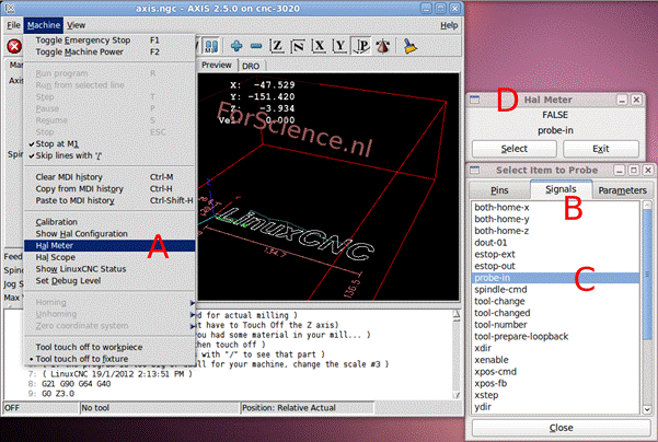
To test the probe open the probe-in signal in the hal meter and tap the ground clip to probe surface. See figure 6.
When you do this, the signal should change from FALSE to TRUE and FALSE again when the clip is released.
References
Thanks
For much valued input to this guide and for his help and expertise in general – Art Eckstein
